E84 Handheld Tster(HHT) 1255
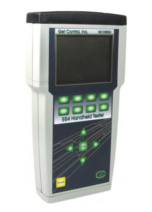
The E84 Handheld Tester (E84 HHT) is the most efficient tool available for quickly testing, trouble-shooting, and resolving E84 problems.
| Product Name | E84 Handheld Tster |
|---|---|
| Model | GCI-05001 |
| Description | The E84 Handheld Tester (E84 HHT) is the most efficient tool available for quickly testing, trouble-shooting, and resolving E84 problems. This self-contained, battery operated tool integrates the industry-leading automated load and unload routines provided in the E84 Emulator. It incorporates a number of industry firsts to quickly locate answers to E84 problems: ・Voltage and current measurement of each E84 signal ・Automated optical transceiver test ・Real-time display of E84 communications using the GCI E84 DLD and RJ-11 Optical Transceiver GCI’s E84 HHT is the portable solution for E84 maintenance, troubleshooting and installation applications. It is an integrated E84 test tool with real-time signal display, voltage and current measurement and test result storage in one easy-to-use instrument. Use the E84 HHT to find fast answers to problems with your E84 interfaces. Its new SD card interface allows test results to be saved and transferred to a PC for further analysis. This interface enhances the organization of results storage, and simplifies the transfer of results to the PC for detailed analysis. Test results are stored as formatted ASCII text files and in binary format compatible with the industry leading GCI E84 Analysis Application. View timing diagrams of E84 signals recorded using the E84 HHT’s standard Load and Unload cycle tests. Due to the quantity of E84 I/O signals and their open-collector logic, standard meter measurement does not provide enough detail to determine E84 fault causes. Signal anomalies that cause E84 interface problems are best examined using analog voltage and current measurements provided by the E84 HHT. The industry standard E84 Test Suite provided by the GCI E84 mulator has also been added to the E84 HHT. Now operators can run through the same series of tests in a troubleshooting environment that were used during tool acceptance testing. |
| Features | ・Menu driven interface ・Internal IR Transceiver ・Supports external IR Transceiver ・Voltage and Current display of each E84 signal ・Automated Active and Passive Load and Unload Tests ・Manual control of each E84 Output with I/O monitoring ・Automated IR Transceiver Testing ・Real-time signal display when connected to a GCI E84 DLD or RJ-11 Optical Transceiver ・EL Backlight ・GCI E84 Emulator Test Suite ・Save test results to SD Flash Card ・Organize test results based on Process Tool ID ・Upload data from GCI E84 DLD to SD Flash Card ・Easily transfer saved data and logged DLD data to PC ・Use GCI E84 Analysis Application to analyze data ・Built-in clock and calendar ・Rechargeable battery ・Firmware is field upgradable |
| Specifications | ・Built-In E84 compliant IR Transceiver ・Active and Passive Electrical E84 interfaces ・DB-25 male (active) and DB-25 female (passive) terminations ・Self-contained rechargeable battery ・SD Flash Card interface ・RS-232 Serial Communications interface ・EL Backlight ・9.3″ × 4.9″ × 1.6″ (236mm × 125 mm × 41mm) |
| Test | Load/Unload Test Perform Load and Unload Tests using the Internal IR to recreate E84 faults. Alternatively, use an External IR device if the IR communications distance exceeds the Internal IR’s one meter range. The E84 HHT plots the E84 signals in real-time as the handoff operation progresses. It prompts for a FOUP (Load) or the removal of the FOUP (Unload) and simultaneously displays a countdown timer. Test results stored to SD Flash Card include test setup details (TA and TP Timer settings, cycle type), test completion status, and the real-time graph. Use the E84 Analysis Application for detailed analysis of the time plot. Optical Transceiver Test Connect an Optical Transcever to the E84 HHT and perform the IR Transcever Test to isolate E84 faults to the transceiver or the process tool. The IR Transceiver Test verifies each optical transceiver signal independently and produces a summary report. Voltage and current measurements can also be displayed for each signal, in both the On and Off states. Failure analysis include tests for shorts between signals, test for shorts between signals and ground, and tests for open signals. Test results stored to SD Flash Card include all voltage and current measurements, pattern test results, and failure analysis error messages in a formatted ASCII text file. Voltage/Current Measurements Connect the E84 HHT directly to the process tool’s E84 Controller to measure and display E84 interface voltage levels. All E84 I/O signals are displayed, including the signal Name, pin assignment, I/O number, and DC voltage measurement. Measurements are displayed in real-time. Switch between Voltage and Current measurement display with a single option button. Select Manual mode to change the E84 HHT’s output states, and monitor the process tool’s response. Save measurements from the current state of the E84 interface to SD Flash Card. Saved test results include all voltage and current measurements for all E84 I/O signals. Test Results Organization Test Results stored on the SD Flash Card are organized by Process Tool ID. Each Process Tool is given an 8 character ID tag. Detailed Process Tool information can be entered to identify individual tools. Process Tool ID’s and Information records can be created / edited on the PC using a standard text editor (Notepad®) and saved to the SCD Card. New Tool ID tags can be created in the FAB using the E84 HHT’s softkey interface. Test Results can be easily transfered to the PC using the included USB SD Card Reader. Test Results are organized as individual files within a standard Windows® folder structure. Most results files can be opened using a text editor or imported into a word processor for report generation. Some files (cycle tests, manual control strip charts) can be viewed using GCI’s E84 Analysis Application. |
Loadport / OHT Track Aligner(Orbital calibrator)
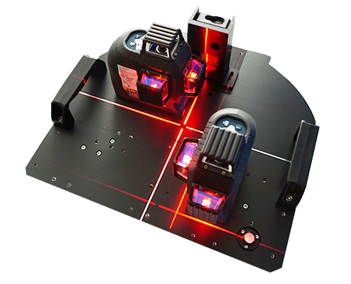
Using carriers and Loadport’s KC pin Location as aligning standard, high-precision line laser to measure OHT track postision. Positioning Fast and efficient.
| Product Name | Loadport / OHT Track Aligner |
|---|---|
| Model | APS-05101 |
| Description | Using carriers and Loadport’s KC pin Location as aligning standard, high-precision line laser to measure OHT track postision. Positioning Fast and efficient. |
| Specifications | ・Power supply : 12 V Li-Ion battery, 4 x 1.5 V LR6 (AA) ・Operating time (max.) : 6 hours (Li-Ion) and 4 hours (4 x AA) in 3-line mode ・Set aligning standard line as request ・Verify the E84 sensor install position ・Verify the Bar-code install position ・Adjusting standard base line fast and easy. ・Quick set up and release, easy to maintenance and repair. ・Using the commercially availible laser liner with the highest accuracy. Customize as request |
Tri-Axial Accelerometer Test Tool(VIB_Test)
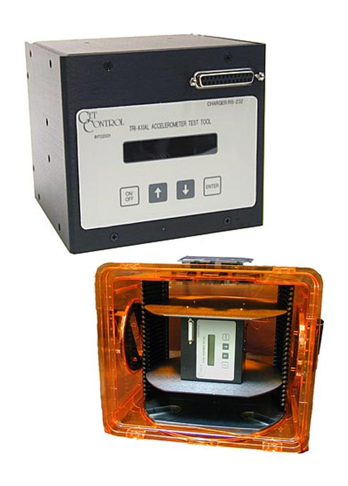
AMHS and conveyor manufacturers utilize the Tri-Axial Accelerometer Test Tool to quantify and qualify the vibration characteristics during development, installation and maintenance of their systems.
| Product Name | Tri-Axial Accelerometer Test Tool |
|---|---|
| Model | APS-05201 |
| Description | AMHS and conveyor manufacturers utilize the Tri-Axial Accelerometer Test Tool to quantify and qualify the vibration characteristics during development, installation and maintenance of their systems. This industry-standard tool is used by 200mm and 300mm FABs to measure the vibration induced to wafer lots by their material handling systems. By detecting the early signs of track misalignment, systems can be maintained to minimize the vibration induced on the wafer lots. The Tri-Axial Accelerometer Test Tool can be used as a stand-alone unit or with the GCI Information Center to provide automated recording using RFID technology. GCI’s Tri-Axial Accelerometer Test Tool provides a precise vibration measurement solution for AMHS suppliers and end users. This tool simultaneously acquires and records vibration data on the X, Y, and Z axes during automated or manual transportation. The Tri-Axial Accelerometer Test Tool is battery operated and self-contained. Adapter plates are included to rigidly mount the tool inside a 300mm FOUP. For 200mm applications, optional mounting plates can be ordered that rigidly mount the tool inside a 200mm wafer carrier. An LCD display and keypad provide access to configuration options. On-board Data Reduction The Tri-Axial Accelerometer Test Tool performs real-time on-board data reduction of 512 data points per second on each axis. Several data reduction options are provided, including RMS, Peak, Frequency at Peak, and True RMS. On-board data reduction is performed on half-second intervals (using FFT’s) producing two reduced data points per second per axis for each reduction type. Recording capacity is limited by reduction type (between two and six hours maximum). Reduced data is stored in battery backed RAM, and is available to upload to a PC until the next recording session is started. An RS-232 port is provided for data upload using a standard terminal application (i.e. Microsoft® Windows Hyperterm). Data is uploaded as formatted ASCII text that can be imported into popular spreadsheet applications for analysis. Time Domain Recording Option The Tri-Axial Accelerometer Test Tool can be optionally configured with the Time Domain Recording option, which records time domain data to a Secure Digital memory card. With this option, Tri-Axial Accelerometer Test Tool records 512 time-domain data points per axis per second directly onto an installed SD Card. Recording capacity is limited by available space on the SD Card (up to a maximum of 24 hours). Data reduction is provided on the PC using GCI’s VibPlot application. VibPlot Analysis Application VibPlot provides tools to perform frequency analysis on the recorded time domain data. VibPlot duplicates the on-board data reduction available in the Tri-Axial Accelerometer Test Tool, plus provides additional analysis features, such as three dimentional waterfall plots, and color spectrograms. The time domain data can be displayed, along with graphs of the reduced data (RMS, Peak, True RMS), and FFT results for each 1/2 second interval. |
| Features | Features Axes ・X, Y, and Z Measurements ・frequency DC to 150Hz ・vibration 0.03g to 2.00g (±0.01g) Batteries / Charger ・rechargeable NiCad battery pack ・advanced battery charging circuit ・lithium battery provides static RAM backup – up to 10 years life (operating time) ・Low-battery sense with warning indicator. Data Analysis Types ・RMS ・peak ・RMS and peak ・RMS, peak, and frequency ・RMS, peak, frequency, true RMS, and N User Interface ・2 × 16 character LCD ・4 key keypad Flash PROM ・stores the system firmware ・easily upgraded using firmware files from GCI (Time Domain Option only) RS-232 Interface ・one RS-232 port is supplied for downloading the recorded data to a host PC. This port is also used for charging the NiCad batteries. |
Tri-Axial Accelerometer Test Tool(VIB_Test)
AMHS and conveyor manufacturers utilize the Tri-Axial Accelerometer Test Tool to quantify and qualify the vibration characteristics during development, installation and maintenance of their systems.
| Product Name | Tri-Axial Accelerometer Test Tool |
|---|---|
| Model | APS-05201 |
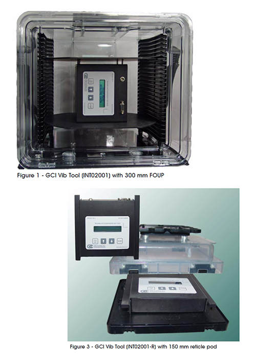
| Description | AMHS and conveyor manufacturers utilize the Tri-Axial Accelerometer Test Tool to quantify and qualify the vibration characteristics during development, installation and maintenance of their systems. This industry-standard tool is used by 200mm and 300mm FABs to measure the vibration induced to wafer lots by their material handling systems. By detecting the early signs of track misalignment, systems can be maintained to minimize the vibration induced on the wafer lots. The Tri-Axial Accelerometer Test Tool can be used as a stand-alone unit or with the GCI Information Center to provide automated recording using RFID technology. |
| GCI’s Tri-Axial Accelerometer Test Tool provides a precise vibration measurement solution for AMHS suppliers and end users. This tool simultaneously acquires and records vibration data on the X, Y, and Z axes during automated or manual transportation. | |
| The Tri-Axial Accelerometer Test Tool is battery operated and self-contained. Adapter plates are included to rigidly mount the tool inside a 300mm FOUP. For 200mm applications, optional mounting plates can be ordered that rigidly mount the tool inside a 200mm wafer carrier. An LCD display and keypad provide access to configuration options. | |
| On-board Data Reduction | |
| The Tri-Axial Accelerometer Test Tool performs real-time on-board data reduction of 512 data points per second on each axis. Several data reduction options are provided, including RMS, Peak, Frequency at Peak, and True RMS. On-board data reduction is performed on half-second intervals (using FFT’s) producing two reduced data points per second per axis for each reduction type. Recording capacity is limited by reduction type (between two and six hours maximum). | |
| Reduced data is stored in battery backed RAM, and is available to upload to a PC until the next recording session is started. An RS-232 port is provided for data upload using a standard terminal application (i.e. Microsoft_ Windows Hyperterm). Data is uploaded as formatted ASCII text that can be imported into popular spreadsheet applications for analysis. | |
| Time Domain Recording Option | |
| The Tri-Axial Accelerometer Test Tool can be optionally configured with the Time Domain Recording option, which records time domain data to a Secure Digital memory card. With this option, Tri-Axial Accelerometer Test Tool records 512 time-domain data points per axis per second directly onto an installed SD Card. Recording capacity is limited by available space on the SD Card (up to a maximum of 24 hours). Data reduction is provided on the PC using GCI’s VibPlot application. | |
| VibPlot Analysis Application | |
| VibPlot provides tools to perform frequency analysis on the recorded time domain data. VibPlot duplicates the on-board data reduction available in the Tri-Axial Accelerometer Test Tool, plus provides additional analysis features, such as three dimentional waterfall plots, and color spectrograms. The time domain data can be displayed, along with graphs of the reduced data (RMS, Peak, True RMS), and FFT results for each 1/2 second interval. | |
| Features | Axes |
| ・ X, Y, and Z | |
| Measurements | |
| ・frequency DC to 150Hz | |
| ・vibration 0.03g to 2.00g (¡Ó0.01g) | |
| Batteries / Charger | |
| ・rechargeable NiCad battery pack | |
| ・advanced battery charging circuit | |
| ・lithium battery provides static RAM backup – up to 10 years life (operating time) | |
| ・Low-battery sense with warning indicator. | |
| Data Analysis Types | |
| ・ RMS | |
| ・peak | |
| ・RMS and peak | |
| ・RMS, peak, and frequency | |
| ・RMS, peak, frequency, true RMS, and N | |
| User Interface | |
| ・ 2 X 16 character LCD | |
| ・ 4 key keypad | |
| Flash PROM | |
| ・stores the system firmware | |
| ・easily upgraded using firmware files from GCI (Time Domain Option only) | |
| RS-232 Interface | |
| ・one RS-232 port is supplied for downloading the recorded data to a host PC. This port is also used for charging the NiCad batteries. |
Carrier Status Monitor Tool
Carrier Status Monitor Tool are able to test and quantify the status inside the carrier, including temperature, humidity and oxygen level.
| Product Name | Carrier Status Monitor Tool (Temperature/Humidity/Oxygen ) |
|---|---|
| Model | APS-05301 |
| Description | Carrier Status Monitor Tool are able to test and quantify the status inside the carrier, including temperature, humidity and oxygen level. Production line can use this tool to verify whether the process tool or storage device with N2 or XCDA purge function are correspond to producting standard. Using an adapter to install inside the carrier firmly and power up with li-ion battery, auto-charging is abailable. Blue-tooth transmission to corresponded Computer with anylysis application and provide internet remote access for collecting data. |
| Features | Working voltage: 12V Power supply: Battery form: lithium battery Humidity measurement range: 0 ~ 100% RH Temperature measurement range: -40 ℃ ~ 105 ℃ Oxygen 0-25%, working temperature 0 ~ 50 ℃ Data record: 1 pen / sec Storage media: SD card. Wireless transmission: Bluetooth |